I have a minimosd (without the kvmod) that I wanted to play with and perhaps run on my fixed wing once I get confident enough to try some FPV. I decided first to try to get it running in standalone mode. This is how the minimosd works without a connection to a flight controller such as the naze32. In this mode, you can only get battery voltage overlay.
First thing is to bridge the 5v partitions. There are 2 pads (one front, one back) that you need to make sure there's a solder connection on.
Then plug the FTDI adapter into the minimosd according to the pinout. As you can see here, they just go straight through on this board.
Then plug the adapter in to your USB port. It will add some drivers. Load up the arduino studio and open the MW_OSD.ino sketch from the MWOSD package you downloaded. In order to work in standalone mode you need to make a few changes in Config.h.
1) #define MINIMOSD
This is the OSD hardware line that should be uncommented.
2) #define NOCONTROLLER
This will get the board to work without a flight controller. If you are using a FC, choose the correct one here.
3) #define FIXEDWING
I am not sure what this does but from the code it looks like it has something to do with a compass/GPS mode.
That's it. Save this and flash it to the board. You'll use Arduino studio and have to select the proper com port and board type. Most likely "Arduino Pro or Pro Mini (5V,16MHz) w/ATmega328"
Now open the MW_OSD_GUI appropriate for your platform and select the correct com port. It should load your MWOSD settings.
First thing is to select and upload fonts (left side). It seems they get corrupted easily. I selected "Display Video Voltage" so that the video power feed is used to display the voltage. This is how you do battery overlay without a FC. If you plugged 5v in from the FC and 12v in from the video input you might burn out the board. There's a stepdown transformer between the 12v side and 5v side but it might blow up if it's fed in both directions.
You need to play with a multimeter to find the right settings for the voltage adjust.
Unless you are using an FC, none of the "Displays" or "HUD" stuff will work. It needs the gyro and mode inputs to display anything. I really just forgot to turn them off in this pic.
You should also put your HAM callsign in there to legally transmit (I, like most people, am using 5.8 GHz for the video link). Make sure to save your settings.
Now plug it in between your camera and your video Tx. The image you receive on the receiver side should have the OSD overlay.
NOTE: The OSD telemetry and the USB by default both use UART1. If you want to be able to use cleanflight while the OSD is plugged in, you need to switch to UART2 and use the RC3/4 pins and have your receiver->FC in PPM mode.
NOTE 2: Also, powering the board using the bridge from the 12v side is not how it is intended to be used. You are meant to power from the 5v side with the bridge and then have the 12v power not plugged in to that side of the board. That said, it does appear to work for me and I haven't burned it out (yet).
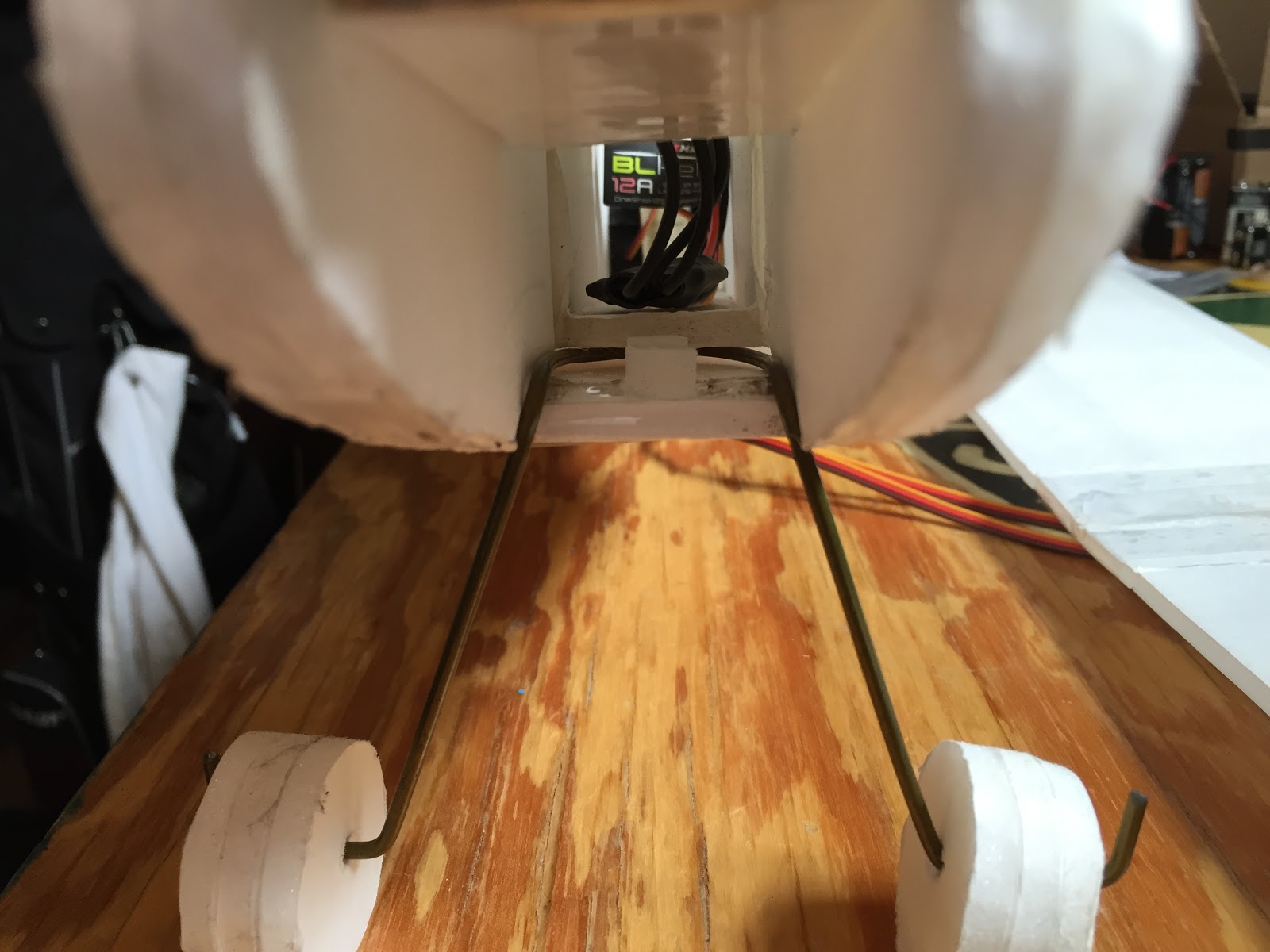
 Notice the gap at the bottom with a little foam piece in the middle


