The main components that I am using are:
- Flight Controller - Naze32 Acro
- Frame - Carbon Fiber ZMR250
- Power Distribution - Lumenier 4power M-PDB
- Receiver - FrSky D4R-ii
- Motors - Emax 1806
- ESC - Afro 12a w/BEC
- Propellers - (10x pairs) Gemfan 5030s
Building the arms
The first step is to attach the motors and ESCs to the arms of the ZMR frame. As this is my first build I elected to solder on bullet connectors for everything so that I can easily change it later if I need to.

I have an arm, motor, an ESC, and some connectors. I attached the connectors to the free ends of the motor you can see and then plugged them together. The trick is to make sure that I straight wired through the 2 CCW motors and crossed wires on the 2 CW motors to ensure that they have the correct directions. The silver nuts are CCW and black nuts are CW as seen from the top.


I put it all together and then folded the wires underneath to make it a bit neater. I ended up zip tying the ESC down to the arm with this configuration.

One of my posts is defective :( I ordered some nylon replacements. If I can find a tap I might ream out a hole.

Building the frame
Arms zip tied down and you can see the frame with posts installed in the background.


There are 8 posts that go in the obvious holes. The ZMR has 2 identical bottom plates that sandwich the arms between them. The arms go in their proper locations based on rotation (front right and back left are CCW, front left and back right are CW) and then screwed in.
Power and boards

Here's an image after the arms are fit. The board there is the PDB with the large pads facing backwards. It is mounted on nylon spacers. The spacer is attached to the bottom board with nylon screws poking up through the board so that the male threaded end sticks up. This allows me to mount the board by pushing it down on to the pin. Also there's just enough space between the bottom plates for the header of the nylon screw and not enough for the threads to fit if I had mounted them the other way.
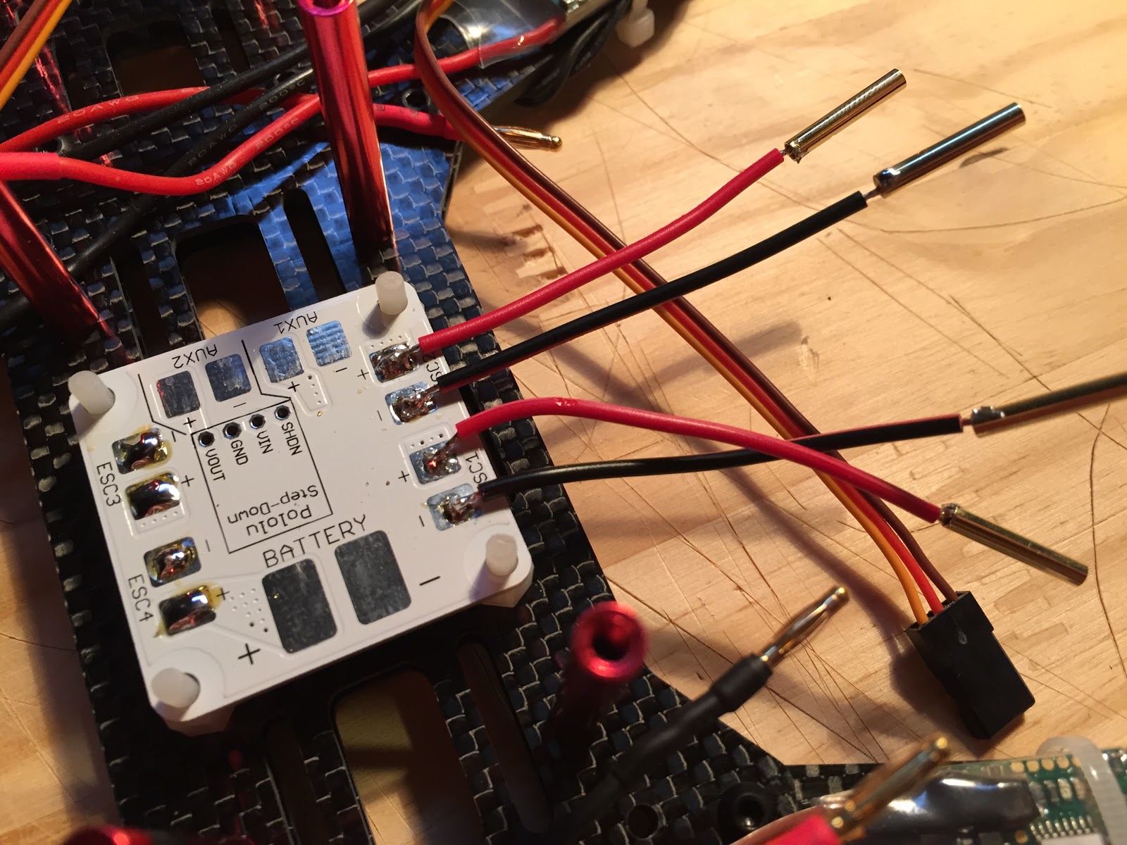
As I decided to use bullets instead of direct soldering, I soldered some 2mm bullets with short leads on to the board. You can see the pads on the other side are tinned and ready to go also.

Soldered and heat shrink applied.

The wires neatly fold back between the board and the posts. They actually connect to the ESC on the opposite side because it makes the wire runs nicer.
Also here you can see the battery connector soldered on. I used 12 gauge silicon wire. Next time I will probably use 14 or 16... it's not easy to solder such large wire down to the flat pads or even to tin them properly.

Dry fit the naze32 board to make sure it all lines up and there's clearance between the power board and the flight controller. Don't want to short anything...


Naze pins soldered. I probably should have just soldered on a servo jumper directly to the pads instead of pins but I didn't. Whoops. I am not super great at soldering and the pins/pads are pretty small, much smaller than the tip of my iron but I managed to get them all done without any accidental bridging or burning much. Some of the joints are good and some are just OK.

Naze32 screwed down, receiver attached. This pic doesn't have it but you need a jumper between the 3/4 signal pins on the receiver to use PPM mode. I am going to mount the receiver to the top plate with some double sided tape. Right above the FC probably.

Top plate on but only with a few screws to see what it looks like.

You can sort of see the how the boards stack here. I am going to turn that receiver around I think and push the antenna through holes in the plate.
Final config and test flight
I plugged in the naze board to my computer and fired up cleanflight. Few things to do here:
1) Calibrate all of the sensors
2) Set it to PPM mode
3) Check motor rotation and calibration
4) Configure channel 5 for mode control (horizon/acro)
Also make sure to configure a switch on the tx to correspond with channel 5.
Then I put some props and a battery on and it flies. When shooting the video I had the tx with throttle in one hand and the camera on the other so I only let it get like an inch off of the floor. The ESCs need calibration but that's easy.
In the next part I am going to add an FPV camera.
No comments:
Post a Comment