It is about setting limits and directions and channel 5/6 for the mode/panic switch. It seems that the Ch5/6 stuff should not be set to 80% as noted in these instructions. I was not getting activation of the different modes when I had it set down to 80 but YMMV.
3) Bind normally
After that, it seems to work. Just make sure that the transmitter is on before plugging the battery in. I have to re-bind it sometimes to make it work.
Binding is just plugging in the plane with the transmitter off and then holding down the bind button when turning it on.
In the last part I built a quadcopter that would work for LOS flying. In this I am going to document my addition of the FPV gear to that frame.
Parts list:
Camera - Runcam PZ0420 (with case, whoops)
Transmitter - Boscam ts832 (would buy a smaller one next time)
OSD - MinimOSD (not the kvmod version, whoops again)
Antennas - FatShark RHCP
FPV install
Here's the gear laid out
Some of these parts go on the quad. The rest is for the ground station.
Transmitter stuff plugged together.
Transmitter stuff and receiver plugged together. It's all working. Now to figure out how to lay it out on the frame.
This pic is kind of bad but so is my layout. I am not entirely sure how to make it all fit in such a way that I can also get to the rx/tx pins on the naze. I had the receiver in a spot where it would block any servo connector connected to the pin headers. I had to move the receiver forward.
It's kind of hard to tell here but there are 2 pins soldered on to the tx/rx pins on the naze. This will send information about the gyros, accelerometers, compass and mode to the OSD.
You can see here the receiver is attached to the top plate right under where the vibration dampeners are. It's attached both with double sided sticky tape and a zip tie.
The OSD is programmed up. and installed with double sided tape attached right to the video tx. I also have a post about how to program the minimOSD if you want to check it out. My camera, OSD, and vtx can all run on 12v so that's how it connects. This has the benefit of allowing the OSD direct access to the battery voltage for display. I don't need to connect up the voltage sense pins on the naze.
Here it is, I think, completed. The camera was attached to the front. I was dumb and accidentally bought a camera with the case which doesn't fit inside the frame. On the up side it will probably not break as easily as the bare board ones do.
I attached it with a zip tie underneath the lens and some double sided tape from the case to the top plate of the frame. It seems unlikely to move on its own. Though it is right out in front, in a perfect place to take the brunt of an impact. We'll see how it works.
As a bonus here's my goggles. I ordered the Quanum V2 from hobbyking in Hong Kong expecting it to take a month or so to arrive but somehow they got here in one day.
I got some parts for Christmas which combined with other stuff I had laying around gives me enough stuff to build a quad copter.
The main components that I am using are:
Flight Controller - Naze32 Acro
Frame - Carbon Fiber ZMR250
Power Distribution - Lumenier 4power M-PDB
Receiver - FrSky D4R-ii
Motors - Emax 1806
ESC - Afro 12a w/BEC
Propellers - (10x pairs) Gemfan 5030s
I also have some camera stuff that I am going to strap on for FPV and a gopro for video recording. I think the FPV camera is some runcam something-or-other. The vTx is a boscam 832. I already have a transmitter (FrSky Taranis) and batteries in various capacities to use.
Building the arms
The first step is to attach the motors and ESCs to the arms of the ZMR frame. As this is my first build I elected to solder on bullet connectors for everything so that I can easily change it later if I need to.
I have an arm, motor, an ESC, and some connectors. I attached the connectors to the free ends of the motor you can see and then plugged them together. The trick is to make sure that I straight wired through the 2 CCW motors and crossed wires on the 2 CW motors to ensure that they have the correct directions. The silver nuts are CCW and black nuts are CW as seen from the top.
I put it all together and then folded the wires underneath to make it a bit neater. I ended up zip tying the ESC down to the arm with this configuration.
One of my posts is defective :( I ordered some nylon replacements. If I can find a tap I might ream out a hole.
Building the frame
Arms zip tied down and you can see the frame with posts installed in the background.
There are 8 posts that go in the obvious holes. The ZMR has 2 identical bottom plates that sandwich the arms between them. The arms go in their proper locations based on rotation (front right and back left are CCW, front left and back right are CW) and then screwed in.
Power and boards
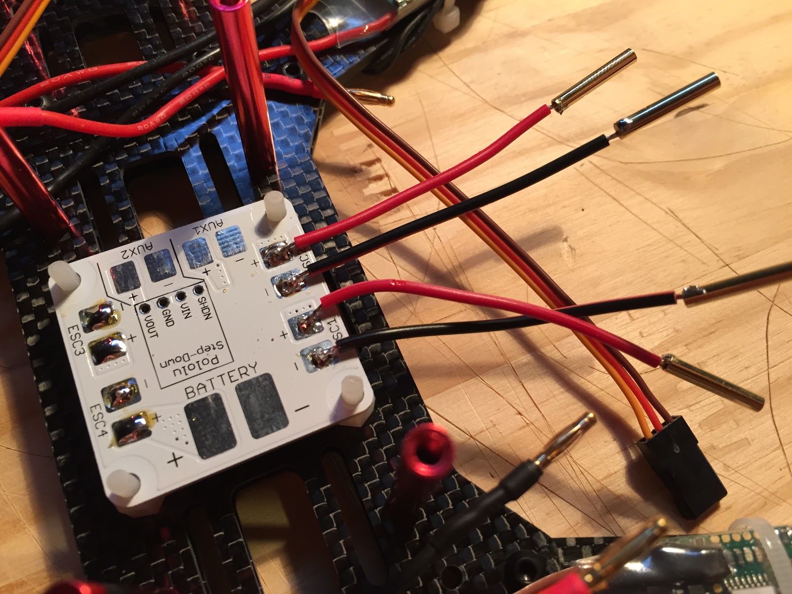
Here's an image after the arms are fit. The board there is the PDB with the large pads facing backwards. It is mounted on nylon spacers. The spacer is attached to the bottom board with nylon screws poking up through the board so that the male threaded end sticks up. This allows me to mount the board by pushing it down on to the pin. Also there's just enough space between the bottom plates for the header of the nylon screw and not enough for the threads to fit if I had mounted them the other way.
As I decided to use bullets instead of direct soldering, I soldered some 2mm bullets with short leads on to the board. You can see the pads on the other side are tinned and ready to go also.
Soldered and heat shrink applied.
The wires neatly fold back between the board and the posts. They actually connect to the ESC on the opposite side because it makes the wire runs nicer.
Also here you can see the battery connector soldered on. I used 12 gauge silicon wire. Next time I will probably use 14 or 16... it's not easy to solder such large wire down to the flat pads or even to tin them properly.
Dry fit the naze32 board to make sure it all lines up and there's clearance between the power board and the flight controller. Don't want to short anything...
Naze pins soldered. I probably should have just soldered on a servo jumper directly to the pads instead of pins but I didn't. Whoops. I am not super great at soldering and the pins/pads are pretty small, much smaller than the tip of my iron but I managed to get them all done without any accidental bridging or burning much. Some of the joints are good and some are just OK.
Naze32 screwed down, receiver attached. This pic doesn't have it but you need a jumper between the 3/4 signal pins on the receiver to use PPM mode. I am going to mount the receiver to the top plate with some double sided tape. Right above the FC probably.
Top plate on but only with a few screws to see what it looks like.
You can sort of see the how the boards stack here. I am going to turn that receiver around I think and push the antenna through holes in the plate.
Final config and test flight
I plugged in the naze board to my computer and fired up cleanflight. Few things to do here:
1) Calibrate all of the sensors
2) Set it to PPM mode
3) Check motor rotation and calibration
4) Configure channel 5 for mode control (horizon/acro)
Also make sure to configure a switch on the tx to correspond with channel 5.
Then I put some props and a battery on and it flies. When shooting the video I had the tx with throttle in one hand and the camera on the other so I only let it get like an inch off of the floor. The ESCs need calibration but that's easy.
I got some small parts to put together a small 5.8 ghz video system to play around with. I attached it to my hubsan x4 like you see below.
I needed to solder on a JST plug to steal power from the main battery for the whole system. Other than that, it's all just rubber banded on.
The fit is REALLY tight. The props hit the camera wires or the antenna if they move slightly off so every crash requires a reset of all of the parts. I should look into transplanting all of the electronics to another frame.
UPDATE (2016-01-22):
I have changed the setup slightly... I now used double sided tape to attach the camera on top and the transmitter on bottom, The wires are wrapped around the body/arms.
None of the wires stick into the props... there is JUST BARELY enough space between the front props and the camera. I am experimenting with where to put the camera to give it a good angle to fly. This thing doesn't have acro mode so the "typical" up angle makes it always look at the sky. It needs to be a little further back than this pic has it. When I go full forward, I am just looking at the ground.
Here's a video of it flying... I dont have a way to capture the view from the onboard camera... yet...
I was bored one evening and had some extra foam board so I decided to try to make a mini RC plane. The Tiny Trainer I have has about a 3 foot wingspan so I aimed for something around 1 foot. I found plans for the Baby Baron. It only uses about 1 board of foam and it uses the same motor pod as the Tiny Trainer. I will need some extra 5g servos though. I did a quick search and then ordered some HXT500s which I think will do it.
All the parts cut out and ready to be assembled.
The sub components together.
Finished airframe.
All together it took about 2-3 hours to cut the plans, cut the parts, and then glue them together. This was my first scratch build. The precision of some of the cut outs is not perfect and the wing seems like it's slightly out of square. The left wing is about 1 degree forward of even. I am sure it will fly well enough.
In order to actually install the electronics, I needed to build new control horns and a firewall. I made them from an old credit card.
They seem to be good enough to move the control surfaces.
Here's a pic of the guts. The receiver is in the back. The esc and the battery are velcro'd to the sides but as close to the centerline as possible.
It seems to balance all right but only a test flight will confirm. The motor is a multistar elite 2204. It's reverse threaded though (I bought CCW as I thought that was normal, but apparently not) so I need some reverse threaded nylock nuts to keep the props on.
I bashed up the powered nose of my Tiny Trainer pretty good so I needed to replace it.
On the flitetest website, you can download plans to build their models. I went to the tiny trainer page and printed out the panels that have the powered nose and doublers.
Apparently when I printed it, I did so at like 103% or something by accident because the longer measurements were off by a bit. The shorter dimensions were close enough to be fine. I had to make the holes for the skewers in slightly different places to make it all work.
A bonus side effect of this mistake was that the nose was about a half cm taller than the old one.
Notice the gap at the bottom with a little foam piece in the middle
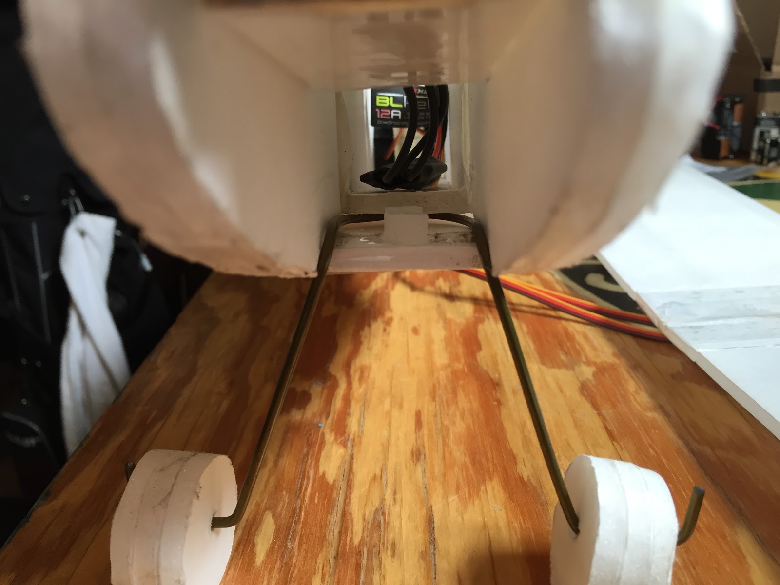
What I decided to do was to use this gap to run a piece of wire hangar through to put wheels on. The hangar goes in from the front and then behind that little foam piece in the middle. The back part of the fuselage comes forward to that piece and retains the wire.
I made some wheels by tracing out D cell batteries and stacking 3 of them to make it thick enough. I drilled a hole in the middle (or close to it) to run the wire through and then bent it up. Since this pic, I added some hot glue balls to the corner between the axles and the upright to keep the wheel from migrating around that bend.
Here it is taxiing across my basement floor. Seems to work well enough.
I have a minimosd (without the kvmod) that I wanted to play with and perhaps run on my fixed wing once I get confident enough to try some FPV. I decided first to try to get it running in standalone mode. This is how the minimosd works without a connection to a flight controller such as the naze32. In this mode, you can only get battery voltage overlay.
First thing is to bridge the 5v partitions. There are 2 pads (one front, one back) that you need to make sure there's a solder connection on.
Then plug the FTDI adapter into the minimosd according to the pinout. As you can see here, they just go straight through on this board.
Then plug the adapter in to your USB port. It will add some drivers. Load up the arduino studio and open the MW_OSD.ino sketch from the MWOSD package you downloaded. In order to work in standalone mode you need to make a few changes in Config.h.
1) #define MINIMOSD
This is the OSD hardware line that should be uncommented.
2) #define NOCONTROLLER
This will get the board to work without a flight controller. If you are using a FC, choose the correct one here.
3) #define FIXEDWING
I am not sure what this does but from the code it looks like it has something to do with a compass/GPS mode.
That's it. Save this and flash it to the board. You'll use Arduino studio and have to select the proper com port and board type. Most likely "Arduino Pro or Pro Mini (5V,16MHz) w/ATmega328"
Now open the MW_OSD_GUI appropriate for your platform and select the correct com port. It should load your MWOSD settings.
First thing is to select and upload fonts (left side). It seems they get corrupted easily. I selected "Display Video Voltage" so that the video power feed is used to display the voltage. This is how you do battery overlay without a FC. If you plugged 5v in from the FC and 12v in from the video input you might burn out the board. There's a stepdown transformer between the 12v side and 5v side but it might blow up if it's fed in both directions.
You need to play with a multimeter to find the right settings for the voltage adjust.
Unless you are using an FC, none of the "Displays" or "HUD" stuff will work. It needs the gyro and mode inputs to display anything. I really just forgot to turn them off in this pic.
You should also put your HAM callsign in there to legally transmit (I, like most people, am using 5.8 GHz for the video link). Make sure to save your settings.
Now plug it in between your camera and your video Tx. The image you receive on the receiver side should have the OSD overlay.
NOTE: The OSD telemetry and the USB by default both use UART1. If you want to be able to use cleanflight while the OSD is plugged in, you need to switch to UART2 and use the RC3/4 pins and have your receiver->FC in PPM mode.
NOTE 2: Also, powering the board using the bridge from the 12v side is not how it is intended to be used. You are meant to power from the 5v side with the bridge and then have the 12v power not plugged in to that side of the board. That said, it does appear to work for me and I haven't burned it out (yet).


